
Intro to AC Power Analysis: Network Analysis
Click for Series List
Part 1: The Basics
Part 2: Network Analysis
Part 3: Cyber Resilience
Let me use the terms “power grid” and “network” interchangeably.
Table of Contents
What is the Power Grid Required to Do?
- Deliver energy to customers, and thereby earn money so that the utilities can profit.
- Deliver power wherever and whenever the customers demand it. That implies maintaining the dynamic balance between energy produced, energy lost, and energy consumed.
- Keep frequency near the nominal 60 (or 50) Hertz, and keep old-fashioned electric clocks on time.
- Keep voltage at all network nodes within the range 90%-110% of nominal, to protect customer and utility equipment from damage.
- Meet several other power quality metrics.
You may object to this list. How can energy and power be separate requirements? They are intimately related because power is the time derivative of energy. Bean counters are interested in kWh energy for billing purposes. But when the customer turns on a 100 watt light bulb, he demands that the grid deliver additional energy to him at the rate of 100 watts; no more, no less, not earlier, not later, but 100 watts right now. The grid designer must satisfy both the bean counter and the customer.
Circuit versus Network Analysis
Students of electricity are first taught how to analyze a circuit. The presumption is that a simple circuit is the most elementary case. We shall see, that’s not true.
Engineers who deal with networks are concerned with the capacity of the network to transport power from point A to point B, regardless of the source of the power or its ultimate destination. In addition, the nature and the quantity of the sources and the loads change all the time. Engineers are also concerned with the behavior of the network, independent of the loads or the generators. Network analysis does not need a complete circuit. In that respect, network analysis is simpler than circuit analysis. I’ll elaborate.
Power Transmission Lines
At this basic level, consider power transmission and power distribution to be the same thing. The electrical parameters of a power line are distributed, with series R per mile, series L per mile, and capacitance C to ground per mile as shown below. The diagram is simplified in that only one of the three phases is shown.
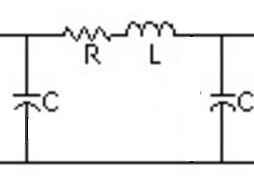
For our purposes, R is so small that we can neglect it. R can be used to calculate real power losses in the transmission. In real life, losses are only about 2% so we can ignore R while studying basics.
Capacitance to ground is a major consideration in ultra-high-voltage lines that run for long distances, and for underground or underwater cables, but for lower voltages and shorter distances, we can neglect C also.
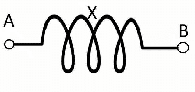
That leaves only the inductance L. Since the frequency is nearly constant 60 (or 50) hertz, it is more useful to write it as the inductive impedance ##X=j\omega L##, where ##\omega##=377 radians/second at 60 hertz (or 314 at 50 hertz).
Finally, we don’t explicitly show the ground connection in the graphic. What we are left with is just X ; it can’t get much simpler than that.
If I say that this is the most complicated circuit you will ever need to understand the basics of the power grid, you will perhaps understand when I say that network analysis is simpler than elementary circuit analysis.
Power and VAR flows
Given the complex voltages ##\bar V_A## and ##\bar V_B##, we can use Ohm’s law to compute the complex current ##\bar I_{AB}##, and the complex power at each end ##P_A+jQ_A## and ##P_B+jQ_B##. The results are complicated expressions that I won’t show, but the following real approximate expressions suffice.
- ##P_A=\frac{V_A\cdot V_B}{X}\sin{\theta}##, where ##\theta## is the phase angle difference between ##\bar V_A## and ##\bar V_B##.
Do not confuse ##\theta## with the angle ##\phi## between voltage and current discussed in Part 1. - ##Q=\frac{V_A \cdot (V_A−V_B)}{X}cos(theta)## or approxumately ##Q \propto (V_A-V_B)##
That leads to the mantra that power engineers learn to chant over and over like “Hare Krishna”.
- Real power flow is proportional to the angle difference between voltages at adjacent nodes.
- VAR flow is proportional to the magnitude difference between voltages at adjacent nodes.
Those principles apply equally to networks with 2 nodes as to networks with 200,000 nodes. If you memorize those two, you are 99% of the way home to understanding the entire power grid.
Now we can generalize. A power grid is a network made up of nodes like A and B, branches that connect the nodes, sources (generators), and sinks (loads). We analyzed just one branch above, but we can repeat that for any branch in an arbitrarily large network. So, no matter how large the network, you only need to know how to analyze one branch at a time. Utility planners use software to routinely analyze networks with 250,000 or more nodes
 .
.
VARs and Voltage Control
If VAR flow depends on voltage magnitude differences, then VARs must be intimately involved with fulfilling grid requirement #4, keeping all node voltages within the range of 90%-110%. We call that voltage control.
Suppose we connected a load at node B, that has an inductance the same value as the transmission line’s X. What would happen? (The load probably has R too but we don’t need to consider that.) It doesn’t take much math to see that we have two equal Xs in series connected to the ground, the voltage at B is 50% of ##V_A##. That would cause a lot of VARs to flow from A to B. It would also violate the 90% – 110% rule. So, what are some possible remedies to fix low voltage?
- We could change the transmission line to reduce X. But if X is too small, then we get into trouble if there is a short circuit with B connected to the ground. So there’s a lower limit on X.
- We could add capacitance in series with X. That leads to the same short circuit problem. It also creates an LC oscillator, and those oscillations might cause their own problems.
- We can increase the voltage at A, but not more than 110%. That would send even more VARs toward B. How do we increase ##V_A##? If there is a power plant at A, we could instruct them to raise the terminal voltage, or (equivalently) to generate more VARs to ship to the grid.
- We could install a transformer between A and B and adjust the turns ratio to increase ##V_B## relative to ##V_A##. But if the customer then disconnects the load at B; ##V_B## might go too high. Special transformers (called TCUL for Tap Changing Under Load) can change their turn ratio dynamically based on remote commands.
- We could connect a capacitance C to the ground at node B. That would put the C in parallel with the load’s X and cancel the load X. This is called reactive shunt compensation. That’s OK unless the load is turned off, leaving only the compensation C without the load. That could cause ##V_B## to go too high.
Shunt compensation comes in capacitive, inductive, or electronic forms capable of both plus and minus Q A so-called synchronous condenser can also be used. It is merely a generator that runs with zero P but plus or minus Q.
All these compensations must deal with changing loads such that ##V_B## stays in the 90% – 110% range. - We could force the customer to reduce his load demand by shutting off all or part of his load because he is causing voltage problems. We call that “load shedding” and we do it only as a last resort since shutting off customers without their permission is highly unpopular.
Capacitive loads are rare but not unheard of. The capacitance of power transmission lines themselves becomes dominant for very high voltage long-distance overhead lines, or for underground or underwater cables. Capacitances to the ground cause high voltages. To remedy high voltage, all the above apply, but in the other direction.
Now, raise your horizon. Think not just of nodes A and B, but of entire regions. The above remedies can be applied equally to entire regions with many external connections and thousands of nodes. If for example, if the entire London Metropolitan Area in England trended toward low voltages, then the grid operator would take action to send more VARs into that region from every direction.
Voltage control costs utilities hundreds of millions of dollars. But keeping voltage 90% – 110% is a utility’s obligation and not something they can explicitly charge customers for. Instead, utilities often attempt to discourage excessive VAR demand by charging punitive fees for power factors that are too low. Power factor can be measured locally by the customer. Charging for power factor rather than Q avoids discussion of that imaginary stuff that many customers believe does not really exist.
Real Power Control
Now, consider this line of logic for a generator at node A.
- The phase angle ##\theta## between two node voltages is proportional to the time integral of the frequency difference between those nodes, and the power flow between those nodes is proportional to ##\theta##.
- The frequency of a generator is directly proportional to its speed in RPM.
- More speed, more kinetic energy. So on an incremental linearized basis, speed is proportional to the integral of the net power on the shaft. Net being the sum of mechanical power in, minus friction losses, minus electrical power out.
To achieve a steady-state, the rate of change of speed and the rate of change of angle must both be zero. That means that the electrical speed (i.e. RPM/N, where N=number of pole pairs) of every generator on the grid must be identical. (We, therefore, call it a synchronous grid.) In a non-steady transient state, we integrate power mismatch once to get frequency, then integrate frequency to get the angle, then feed power as a function of the angle it back with a minus sign. That is a description of a classical second-order harmonic oscillator. Indeed, generators on power grids typically perform like lightly damped oscillators.
The good news is that every generation can measure the local frequency. It is directly
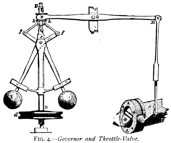
proportional to RPM. That suggests a very simple and completely distributed way to regulate power on the whole grid. We simply apply James Watt’s 1788 invention, the flyball governor, to each generator. It varies mechanical power in response to speed changes. Then we tune the gain of these governors, to be the same in percent, for every generator. Thereafter, if we add load to the grid, the frequency will start to drop. The speed governors will open the throttles to make more power, with each generator inherently taking up its proportional share of the load until mechanical power (less losses) and electrical power are exactly balanced once again.
I think it’s very cool. Using centuries-old technology, we can achieve an exquisitely sensitive dynamic balance between total generation produced (minus losses) and total load consumed, all distributed over an arbitrarily large geographic area. In the same stroke, we have satisfied grid requirements #2 and #3. Hats off to the engineers of yesteryear.
We stopped using flyballs in the 70s. A modern electronic implementation of a speed governor can be done with a single operational amplifier. It could hardly be simpler. This robust distributed scheme kept all the US’ grids operating without a single regional blackout from about 1889 until November 9, 1965 (the date of The Great Northeast Blackout). Even today despite all our computers, the speed governor is the primary regulator of power grids. It is inherently distributed. It does not need remote communications of any kind. It is not digital. It is very difficult to attack via remote means.
—
PF members sophiecentaur, and Jim Hardy contributed to this article.
Dick Mills is a retired analytical power engineer. Power plant training simulators, power system analysis software, fault-tree analysis, nuclear fuel management, process optimization, power grid operations, and the integration of energy markets into operation software, were his fields. All those things were analytical. None of them were hands-on.
Dick has also been an exterminator, a fire fighter, an airplane and glider pilot, a carney, and an active toastmaster.
During the years 2005-2017. Dick lived and cruised full-time aboard the sailing vessel Tarwathie (see my avatar picture). That was very hands on. During that time, Dick became a student of Leonard Susskind and a physics buff. Dick’s blog (no longer active) is at dickandlibby.blogspot.com, there are more than 2700 articles on that blog relating the the cruising life.


No I havent read this article I'm a bit new here and try to find my way. Thanks for the recommendation. I love this subject as well very much.
Thank you for the questions. As you can tell, I like these subjects.
But this all makes me curious how the gird analyser (if so) communicates) with the power plants? I would think there must be some communication somewhere. As loads fluctuates during the day and seasons like rush hour, factories starting in the morning, summer & winter differences.Have you read this? https://www.physicsforums.com/insights/what-happens-when-you-flip-the-light-switch/
It gives and overview of the whole process.
@anorlunda ,
Wow what a very nice explanation! I hope you were not offended maybe I wrote my message a bit harsh but that was surely not the intention. I just love my job and always want to learn more. Funny thing I noticed here that i even didnt know that there is a clear difference between a transmission line or a bus (which i see the most). In my work I dont think further as the differential protection of a step-up strafo and synchronization to the grid. We pump in the net what is allowed or requested.
This is a completely different point of view as for someone who doing grid analysis. This is very clear now to me, which must be an awesome job by the way ;)
But this all makes me curious how the gird analyser (if so) communicates) with the power plants? I would think there must be some communication somewhere. As loads fluctuates during the day and seasons like rush hour, factories starting in the morning, summer & winter differences.
Im also very happy to know that it was Steinmetz who "invented" the way we can calculate easy with loads. Im using this on a daily base without knowing where it came from. So thanks for that as well.
I can't look in your agenda but a follow up on your articles would be very cool. But will create most probably more interesting questions en will surely be a pleasure to read.
Thanks for your clear explanation
I shouldn't be surprised by your confusion. The viewpoint of the grid operators and the power plant operators are very different, and there is not much cross-training.
Connected to the Euro grid, you feel like a drop of water in an ocean. But suppose that all generators in Europe were ordered to raise their terminal voltages by the same amount at the same time. If all generators act in unison, then the behavior of the continent is more like that of a ship at sea but at a larger scale. More important and more realistic, suppose you are ordered to raise voltage and another plant on the other side of the continent is ordered to lower voltage at the same time. What would the effect of that be? Why would the grid operators order that? Those are questions that can't be answered solely from the viewpoint of a single power plant.
View attachment 140081
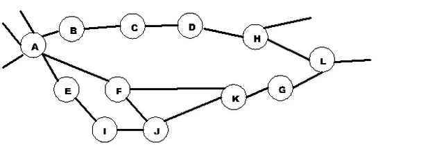
Consider the power grid to be like a copper window screen. Each place where two wires cross and connect, is a node (call it a bus if you like). Each strand of copper between nodes is a transmission line. The distinctive feature of the grid is that there are very many paths connecting every node to every other node (even if there are numerous broken strands).
The job of the power plant operator (or the load manager) is to focus on how many MW and MVAR are injected or withdrawn from the grid at their local node. The job of the grid analyst (explained in the Insights article), is to calculate the voltages at all nodes and the flows of MW and MVAR through all the wire strands, regardless of which nodes are generators and which are loads.
The formulas in the Insights article calculate MVAR flow as a function of the voltage difference between nodes. How do you see that in your power plant? You don't. You probably don't even have a measurement of the voltage at the "other end" of the transmission line you connect to. In fact, you probably connect to several lines so that there are several "other ends".
But from a logical sense, what happens if you raise the terminal voltage at your plant by 1%? It is reasonable that the voltage at the "other end" of the transmission line also raises. However it will probably raise less than 1%, therefore the voltage difference between the two ends of that line will increase. It is those differences used in the formulas (angle difference for MW and voltage difference for MVAR), something that you can't measure locally at your plant.
How does the grid analyst account for the generator at the power plant node? He doesn't. It makes no difference to the analyst if there is a synchronous generator with field windings, or batteries, or solar panels, or whatever. It is just a node. The formulas are written so that any amount of MW and MVAR (plus or minus) may be injected or withdrawn at any node.
So the article was written purely from the point of view of grid analysis, deliberately ignoring the details of the power plants. So no wonder that it sounds alien to you. Of course real life grid controls take account of the specific transient capabilities of each plant, but that is "advanced control" the article's ambition was to only explain "basic control."
My target audience was neither power plant operators nor grid operators, but rather people who know about electric circuits, and who get puzzled when they try to apply Ohm's law, KCL and KVL to understand how the national power grid works. I'm also a bit of a history fan, so it delights me to say that if I had written that article in 1888 rather than 2016, not a single word would have to change.
Perhaps I should write a part 4 to the AC Power Analysis series to elaborate on the questions you ask. It could be fun and useful for cross training. "Ying and Yang: Grid operations for power plant operators, and power plant operations for grid operators."
View attachment 140129
I hope this thread is not to old to add some comments here. I work for some years now as a commissioning engineer of synchronous generators and your document I should have read many years ago it is very interesting. But as others the two wonderfull formulas to calculate P and Q confuses me a bit. As well I like to mention that it is not rare units supply to one factory. But in this whole discussion there's not mentioned any difference between Island mode and Grid mode. Island mode you see a lot e.g. ships, countries with unreliable grid where factories disconnect when things get bad and there are more situation.
As far I understand i need more field current when load is increased (P or Qind). The reason you need to excite more when P is increased is because the terminal voltage tends to drop or sufficient reactive power needs to be exported.
Connected to the grid and assuming it is a "infinite strong grid" which means that my 1 generator can not influence the voltage of the grid result in a different scenario. If connected to such a grid and I increase my field current I will start to export more reactive power (leading current) the opposite happens when I decrease the field current.
For that reason I dont understand the two formulas. Maybe I look to it from a completely different and therefore wrong point of view. But I was taught that a big grid like we have in europe e.g. you cant change the voltage. But here we express the amount of Q in relation to voltage difference and reactance?
Is anybody willing to clarify this a bit more?
Thanks a lot
Yes still valid.
[QUOTE=”anorlunda, post: 5436473, member: 455902″]
[LIST]
[*]It is rare for one generator to supply one factory. Think of the whole grid providing the supply.
[*]The generator field is part of the voltage regulator loop. It will probably increase because extra VARs will be needed.
[*]The generators main response to the motor will be to increase its angle.
[/LIST]
[/QUOTE]
Thank you for your reply. Small grids with only one or two generators running in parallel are very rare but are the rule in merchant and military navy. At these small grids the proposition that the flow of reactive power is proportional to voltage difference is still valid?
[QUOTE=”larsa, post: 5436365, member: 588822″]What you wrote is very helpful. I want to ask you something. Suppose that we have a generator that supplies electric power to a factory. When the workers of the factory start a motor, in order for a magnetic field to be created at the stator of the motor the stator of the generator is demagnetized. So the field current of the generator is increased in order to compensate. Is this correct?[/QUOTE]
[LIST]
[*]It is rare for one generator to supply one factory. Think of the whole grid providing the supply.
[*]The generator field is part of the voltage regulator loop. It will probably increase because extra VARs will be needed.
[*]The generators main response to the motor will be to increase its angle.
[*]Power generated does not come from the field. It is theoretically possible (but impractical) to use permanent magnets for the field. So you should stop thinking more power more field.
[/LIST]
[QUOTE=”anorlunda, post: 5429045, member: 455902″]You can see a tutorial here, [URL]http://www.pjm.com/~/media/training/new-pjm-cert-exams/bet-lesson5-power-flow-on-ac-transmission-lines.ashx[/URL]
and a derivation of the equations here, [URL]http://home.eng.iastate.edu/~jdm/ee553/DCPowerFlowEquations.pdf[/URL]
The article gives ##P=frac{V_Acdot V_B}{X}sin(theta)##.
The equation for Q is ##Q=frac{V_Acdot (V_A-V_B)}{X}cos(theta)##
but where ##V_A## and ##cos(theta)## are both close to one,
the approximate equation is ##Q=frac{(V_A-V_B)}{X}##
Note that both of these equations use only ##V_A##, ##V_B##, and ##X##. We don’t need to know the load resistance. That is why I try to discourage thinking about a load R at all. Focus on ##V_A##, ##V_B##, and ##X##
I could assume that the load is some computer controlled device that manipulates stuff to draw the P and Q that it wants. If the load P and Q do not vary with ##V_B## then the load is not an impedance or a resistance. The load is just a load and how the load varies with voltage or frequency we don’t know, but we don’t need to know to calculate P and Q as above. So once again, I urge [I]forget the load R.[/I][/QUOTE]
What you wrote is very helpful. I want to ask you something. Suppose that we have a generator that supplies electric power to a factory. When the workers of the factory start a motor, in order for a magnetic field to be created at the stator of the motor the stator of the generator is demagnetized. So the field current of the generator is increased in order to compensate. Is this correct?
You can see a tutorial here, [URL]http://www.pjm.com/~/media/training/new-pjm-cert-exams/bet-lesson5-power-flow-on-ac-transmission-lines.ashx[/URL]
and a derivation of the equations here, [URL]http://home.eng.iastate.edu/~jdm/ee553/DCPowerFlowEquations.pdf[/URL]
The article gives ##P=frac{V_Acdot V_B}{X}sin(theta)##.
The equation for Q is ##Q=frac{V_Acdot (V_A-V_B)}{X}cos(theta)##
but where ##V_A## and ##cos(theta)## are both close to one,
the approximate equation is ##Q=frac{(V_A-V_B)}{X}##
Note that both of these equations use only ##V_A##, ##V_B##, and ##X##. We don’t need to know the load resistance. That is why I try to discourage thinking about a load R at all. Focus on ##V_A##, ##V_B##, and ##X##
I could assume that the load is some computer controlled device that manipulates stuff to draw the P and Q that it wants. If the load P and Q do not vary with ##V_B## then the load is not an impedance or a resistance. The load is just a load and how the load varies with voltage or frequency we don’t know, but we don’t need to know to calculate P and Q as above. So once again, I urge [I]forget the load R.[/I]
[ATTACH=full]98331[/ATTACH] [ATTACH=full]98332[/ATTACH] [ATTACH=full]98332[/ATTACH] [ATTACH=full]98333[/ATTACH]
Source voltage is 10V. You can see increase in load angle (by increasing the load) increases the active power (from bottom to top) but reduces the load voltage.
[QUOTE=”larsa, post: 5428991, member: 588822″]What you wrote is helpful. If i understand your point, the voltage difference is due to a time difference between generator voltage and load voltage. But this phase/time difference is the cause of the real power as well according to the elegant analysis of the article which i don’t understand[/QUOTE]
ahhhh. so I answered the wrong question… my apologies.. I’ll try to get you an answer
edit. to be honest. I’m having trouble coming up with a simple explanation. Einstein said if you can’t explain it simply, you don’t understand it well enough. I guess I need to hit the books.
[QUOTE=”donpacino, post: 5428982, member: 341479″]imagine an AC voltage source with an inductor and resistor in series. The inductor will resist change in current.
You can analyze this in the time or frequency domain. Looking at it in the frequency domain, the inductor will impart a phase shift on that signal. The larger the inductor is in relation to the resistor, the closer that phase shift will move to 90 degrees. Keep in mind at 90 degrees, the power would be purely reactive. At 0, the power would be purely real (at zero it would just be a resistor).
A phase shift translates to a time delay in the time domain. with no time delay the sin waves will be the same (pure real power. With some time delay the power will lag slightly, because one signal lags, the difference between the 2 voltages will increase, proportionally to the reactive power (the closer to 90 degrees you get, the greater the instantaneous difference, and the greater the reactive power).
note: i personally think that power is driven by the voltage and current, and the difference between voltages. But thats how I think of it. Voltage is MUCH easier to measure than current.[/QUOTE]
What you wrote is helpful. If i understand your point, the voltage difference is due to a time difference between generator voltage and load voltage. But this phase/time difference is the cause of the real power as well according to the elegant analysis of the article which i don’t understand
[QUOTE=”larsa, post: 5428981, member: 588822″]Thank you for your comment. But if resistance of load is responsible for reactive power flow, what is responsible for flow of active power?[/QUOTE]
The difference between angles of V[SUB]source[/SUB] and V[SUB]load[/SUB] i.e. δ determines the active power. At δ=90°, you get maximum active power. But that reduces the terminal voltage much below the permissible limit and satbility is compromised. So, δ is kept 15-20°.
[QUOTE=”larsa, post: 5428960, member: 588822″]Could you please explain a bit more the proposition that flow of reactive power is proportional to the magnitude of voltage difference between nodes?[/QUOTE]
imagine an AC voltage source with an inductor and resistor in series. The inductor will resist change in current.
You can analyze this in the time or frequency domain. Looking at it in the frequency domain, the inductor will impart a phase shift on that signal. The larger the inductor is in relation to the resistor, the closer that phase shift will move to 90 degrees. Keep in mind at 90 degrees, the power would be purely reactive. At 0, the power would be purely real (at zero it would just be a resistor).
A phase shift translates to a time delay in the time domain. with no time delay the sin waves will be the same (pure real power. With some time delay the power will lag slightly, because one signal lags, the difference between the 2 voltages will increase, proportionally to the reactive power (the closer to 90 degrees you get, the greater the instantaneous difference, and the greater the reactive power).
note: i personally think that power is driven by the voltage and current, and the difference between voltages. But thats how I think of it. Voltage is MUCH easier to measure than current.
[QUOTE=”cnh1995, post: 5428977, member: 552336″]Let me see if I understood it correctly.
Suppose a purely resistive load R is fed from an ac supply V through a transmission line with reactance X(negligible resistance). Transmission line reactance X is fixed. Now if load R is increased, more current is drawn from the supply. This causes a voltage drop across X and load voltage is reduced, increasing the difference V[SUB]source[/SUB]-V[SUB]load[/SUB]. If the load is decreased, voltage across the load increases and V[SUB]source[/SUB]-V[SUB]load[/SUB] decreases, reducing the reactive power flow.[/QUOTE]
Thank you for your comment. But if resistance of load is responsible for reactive power flow, what is responsible for flow of active power?
[QUOTE=”larsa, post: 5428960, member: 588822″]Could you please explain a bit more the proposition that flow of reactive power is proportional to the magnitude of voltage difference between nodes?[/QUOTE]
Let me see if I understood it correctly.
Suppose a purely resistive load R is fed from an ac supply V through a transmission line with reactance X(negligible resistance). Transmission line reactance X is fixed. Now if load R is increased, more current is drawn from the supply. This causes a voltage drop across X and load voltage is reduced, increasing the difference V[SUB]source[/SUB]-V[SUB]load[/SUB]. If the load is decreased, voltage across the load increases and V[SUB]source[/SUB]-V[SUB]load[/SUB] decreases, reducing the reactive power flow.
Could you please explain a bit more the proposition that flow of reactive power is proportional to the magnitude of voltage difference between nodes?
Sure glad we have a genuine power system guy here . I’ve only looked over the shoulders of some.
[QUOTE=”anorlunda, post: 5426672, member: 455902″]discussion of the grid is inherently multidisciplinary.[/QUOTE]
Electrical, mechanical, control theory(downright right burly math – search on “Power System Stabilizer”), and a rapidly increasing share of computer science.
Thanks for the kind words.
[QUOTE=”donpacino, post: 5426656, member: 341479″]Have you thought about writing on piece on the effects of an increase in distributed loads such as windmills, solar panels, home battery banks (for off peak energy use) and plug in hybrid/electric vehicles on the grid? Particularly their effect on the operation and operation philosophy of grid control companies?[/QUOTE]
I’ll give that some thought. If I did write such an article, it will cover both engineering and economics. As you can already see perhaps, discussion of the grid is inherently multidisciplinary.
I like those two articles. They provides a good explanation of a concept that can be very confusing.
Have you thought about writing on piece on the effects of an increase in distributed loads such as windmills, solar panels, home battery banks (for off peak energy use) and plug in hybrid/electric vehicles on the grid? Particularly their effect on the operation and operation philosophy of grid control companies?
The reason I ask is I feel with your background you might be able to tackle that problem.
Jim Hardy suggested a mechanical analogy that did not make it into the article.
Imaging a cylindrical rotating shaft. How do we know if it is transmitting power from one end to the other?
Stop the rotation, and paint a dotted line along the top surface. Then rotate again with you riding on the shaft like a rider on a horse. The shaft appears stationary to you. If the shaft is transmitting power from my end to the far end, it will twist and I can see the twist because of the dotted line. If the far end ships power to my end, the shaft twists the other way. Twist is another way of saying that the angle at my end is different than the angle at the far end.
To increase the twist, i make the RPM at my end slightly faster than at the far end for a short duration. To do that, I must temporarily put in more power at my end, then return the power to the previous value.
In the steady state, when twist is not changing. I can state with certainty that the RPM at my end is identical to RPM at the far end, and I don’t need a computer to figure that out.
It would be possible to send the same power down the shaft at different RPMs, so making the twist stop changing and making the RPMs return to normal, are two independent goals.
What happens if load at the far end increases? Both ends of the shaft will start slowing down. I’ll have to put more power in at my end, until the angle stops changing and the RPM is back to normal. When I get there, I should see that the twist has increased, and that the extra amount of power I need to achieve that, exactly matches the increase in load power.
Which angle is zero? It doesn’t matter. Twist is the same, no matter what angle you choose to be zero.
A shaft has only two ends, but the power grid has many nodes with an angle at each node, so the analogy is not perfect. Analogies never are. The analogy is also primarily DC, and it does nothing to help us understand VARs, unless we start adding springs, flywheels, and oscillators making a simple analogy complicated.
[QUOTE=”Greg Bernhardt, post: 5426579, member: 1″]Very interesting topic I never gave much thought to. Looking forward to the third part.[/QUOTE]
We all take infrastructure for granted as long as it’s working.
Very interesting topic I never gave much thought to. Looking forward to the third part.
Part 1 was amazing! Can’t wait to dig into this one :smile:
Could you please explain a bit more the proposition that flow of reactive power is proportional to the magnitude of voltage difference between nodes?