
Introduction to Pitot-Static Systems in Gliders
Like many others, I have been seeking new and fun things to do during a pandemic. I decided on the new Microsoft Flight Simulator 2020, but the Condor 2 Soaring Simulator is my intermediate step. I am certified as a pilot, including gliders, but I have not flown for many years because of the expense. These simulators will allow me to join much of the fun and to greatly increase my skills, while semi-quarantined.
Of course, physics is vitally important to all pilots, but in a glider, it is more so. Much more so. Especially cross-country racing in a glider requires extensive knowledge of physics and use of mathematics. As an engineer, I am also interested in the design of the instruments and procedures as well as their use. What I discovered after some brief research is that the use of air pressure in aircraft avionics is a topic including the old and new, the smart and dumb, man versus machine, as well as the universal engineering qualities common to any instrument: Accuracy, Reliability, Ergonomics.
Engineers, get ready, this should be a fun topic even if you never saw a glider.
Table of Contents
The Barometer, the Pitot, and the Venturi
A manometer measures the difference in two pressures. A barometer measures atmospheric pressure. We typically illustrate those with U-shaped glass tubes filled with liquid, but in instruments, we use a bellows or a diaphragm which transforms a pressure difference into a mechanical motion.
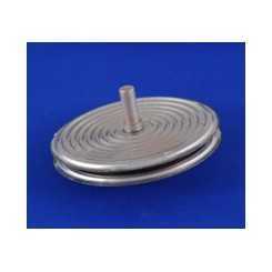
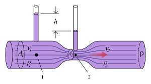
The venturi is used to transform fluid flow into pressure difference, which can be further transformed into mechanical motion with a bellows.
A pitot tube is a pipe that is mounted on an aircraft, usually facing forward. The Pressure in the pitot (called dynamic pressure) varies with the speed of the aircraft relative to the air mass.
We can add a second port that is oriented at nearly 90 degrees from the direction of motion. That is called a static port. A pitot-static tube has both the pitot port and the static port. The pressure difference between the two is a basis for airspeed measurements.
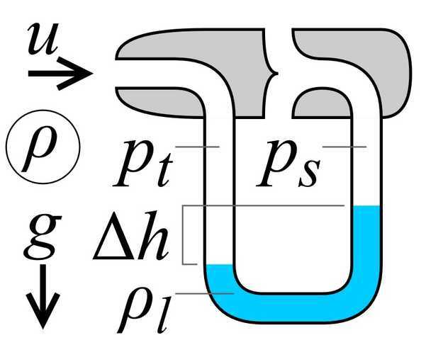 In the illustration, we see a pitot-static tube and a manometer. ##p_t## is the dynamic pressure, ##p_s## is the static pressure, ##\Delta h## is proportional to ##p_t – p_s##, ##u## is the velocity of the tube relative to the air mass. Equations show that ##u\propto \sqrt h## and that kinetic energy ##K.E. \propto h##
Altitude, Airspeed, Rate of Climb
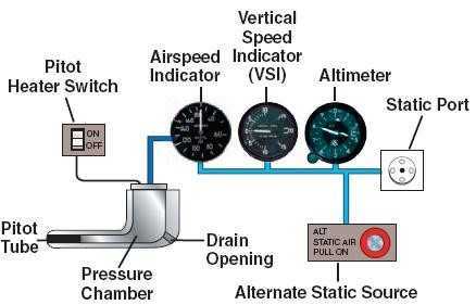 The classical pitot-static system for an airplane is used to provide three instruments important to a pilot: airspeed, altitude, and vertical speed.
By convention, airliners worldwide communicate in English and measure altitude in feet, airspeed in knots, and VSI in feet per second. But gliders do not need spherical navigation, nor international flights. Most gliders use meters, kilometers per hour, and meters per second.
Note that airspeed is motion relative to the air mass. Ditto for vertical speed.
Ground speed is motion relative to the ground, and today we measure that with GPS. It is based on the difference between dynamic pressure and static pressure.
Altitude is measured by barometric pressure. A little knob on the altimeter adjusts for the local barometric pressure. When that knob is set correctly, the altitude should read zero when at sea level. We call that MSL altitude (Mean Sea Level) as opposed to AGL (above ground level) altitude. If you are flying past the summit of Mount Everest, both MSL and AGL altitudes are critically important to the pilot. AGL altitude can also be measured by radar.
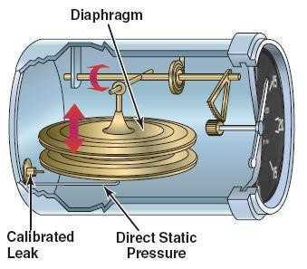
Vertical speed (VSI) uses only static pressure. It should measure the rate of change of static pressure. How do you do that mechanically? You simply have a barometer with a calibrated leak. The leak assures that if altitude is not changing, the indicator will eventually point at zero. In the illustration to the right, if the calibrated leak is closed off, we have an altimeter. If it is open, we have a VSI.
Accuracy & Reliability
The accuracy of a pitot-static system depends on many factors. One obvious one is that the nose of the aircraft may not point in exactly the same direction as the plane’s motion. It could have a sideslip both vertically and horizontally. Also, the value static pressure can depend on where the static port is placed on the plane, and each location may behave differently when the plane climbs or slips, or stalls. Some gliders have as many as 8 static ports. Pilots are cautioned that a transient such as an abrupt pull-up can also temporarily distort readings.
To the pilot, those instruments are critical. They must be extremely reliable. Redundancy is one way to improve reliability. If they are electronic, loss of power and RF interference could be threats. Pneumatic instruments are vulnerable to blockages or leaks in the plumbing. The tragic crash of Air France flight 447, was triggered by ice blockage in the pitot tube. In modern times, simple aircraft like gliders use pneumatic systems, while airliners use electronic digital electronics and software plus pneumatic. A digital system could provide synthetic estimates of airspeed, altitude, and VSI based on non-air pressure measurements, plus GPS and inertial measurements.
Total Energy Compensated Vario
In a powered airplane, the pilot needs to know vertical speed, VSI. For example, he may set the autopilot to climb at 1000 feet per second. A glider pilot is more interested in energy rather than vertical speed.
A glider has relatively little drag, so assume for the moment zero drag. Suppose we start with the initial condition of altitude A and speed S. If he aims the nose down, the glider starts losing altitude but gaining speed. He could then point the nose up again and use that speed to return to altitude A and speed S because the total energy, kinetic plus potential is conserved (assuming zero drag). On the other hand, in a rising air mass, it adds energy to the glider from an external source. That is what the glider pilot seeks, a place where energy will be added. He also avoids places that subtract energy.
Start with ##T.E.=K.E.+P.E.##. Total energy equals kinetic energy plus potential energy. We can say the same about changes in energy ##\frac{\Delta T.E.}{\Delta t}=\frac{\Delta K.E.}{\Delta t}+\frac{\Delta P.E.}{\Delta t}##.
But ##P.E.=mgh## where ##m## means mass, ##g## means the local acceleration of gravity, and ##h## is height.
And ##K.E.=\frac{1}{2}mV^2##, where ##m## means mass, and ##V## means speed.
So, ##\frac{\Delta T.E.}{\Delta t}=\frac{m\Delta V^2}{2\Delta t}+\frac{mg\Delta h}{\Delta t}## and the quantity desired.
The clever part is to scale that energy measurement by the constant ##mg##, leaving:
##\frac{\Delta T.E.}{mg\Delta t}=\frac{\Delta V^2}{2g\Delta t}+\frac{\Delta h}{\Delta t}## which has units of meters per second.
That is called “total energy compensated vertical speed”. The instrument that does that we call a Vario. It differs from the VSI on an airplane even though the units are the same. Pilots are not used to working with joules, but they are familiar with meters per second. I consider that a clever form of ergonomics.
If we have a theoretically perfect vario, then climbing or diving does not cause the vario needle to move at all but entering an air mass with rising or sinking air does make it move. That’s the purpose.
The Vario
So how do we accomplish the energy compensated vario pneumatically? A direct approach uses altitude to estimate and airspeed to estimate and to perform the sum ##\frac{\Delta V^2}{2g\Delta t}+\frac{\Delta h}{\Delta t}## electronically or pneumatically.
An indirect direct method uses a third, rearward facing pitot port.
Total Energy probes are typically mounted on the vertical fin. The port(s) face backward, so Total Pressure – Static Pressure is a negative quantity. In other words, Dynamic Pressure measured this way is a negative number whose magnitude increases with airspeed. Recall that Dynamic Pressure is linearly related to kinetic energy. The elegant result is that, as the pilot pulls back on the stick, the Static Pressure decrease is matched by the decrease in the magnitude of the negative Dynamic Pressure. In other words, the increase in potential energy (decrease in Static Pressure) is matched by the decrease in negative kinetic energy. Ponder that & smile! A modern glider efficiently translates Kinetic to Potential energy and vice-versa. The result is a single quantity that is neither dynamic nor static pressure but is invariant to exchanges between potential and kinetic energy induced by the pilot. Connect a TE probe to a pressure gauge, compute the rate of change, and Voila, you have a Total Energy (TE) variometer. – https://clearnav.net/Technical/Variometer-pneumatics.pdf
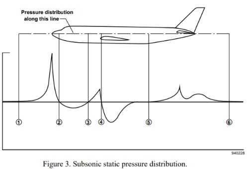
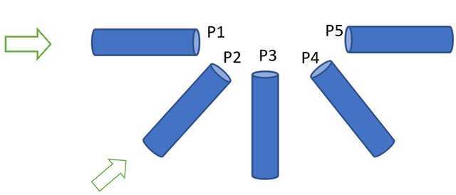
Engineers can generalize on the idea. Suppose we had a multi-port pitot with 5 tubes oriented as shown. The arrow shows the direction of motion of the air relative to the apparatus. P1..P5 are five pressures we can measure, some positive some negative with respect to ambient.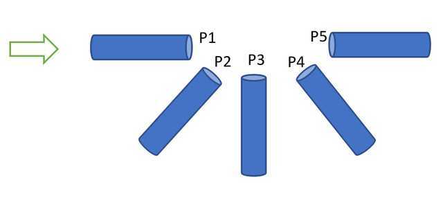
- P3 can be used for altitude
- P1-P3 for airspeed
- P3-P5 for an indirectly energy compensated vario.
- P2 and P4 can be used for angle-of-attack as we’ll see later.
The Netto Vario
This advanced vario also compensates for the intrinsic sink rate of the glider, thus making a still more accurate vario which should move its needle off zero only for rising or sinking air masses. We’ll talk about the polar curve later.
Paul MacCready
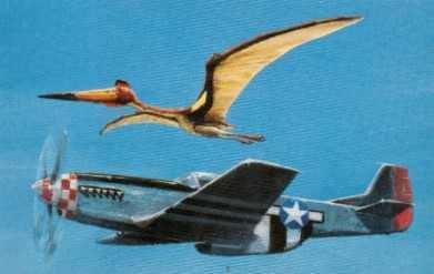 Paul MacCready was a remarkable engineer. He was a three-time winner (1948, 1949, 1953) of the Richard C. du Pont Memorial Trophy, awarded annually to the U.S. National Open Class Soaring Champion. In 1956, he became the first American pilot to become the World Soaring Champion. He created a human-powered aircraft, the Gossamer Condor. He later created solar-powered aircraft such as the Gossamer Penguin and the Solar Challenger.[8] He was involved in the development of NASA’s solar-powered flying wings such as the Helios, which surpassed the SR-71‘s altitude records and could theoretically fly on Mars (where the atmosphere is thin and has little oxygen).[9] MacCready also collaborated with General Motors on the design of the Sunraycer, a solar-powered car, and then on the EV-1 electric car. In 1985, he was commissioned to build a halfscale[11] working replica of the pterosaur Quetzalcoatlus for the Smithsonian Institution.
But the MacCready invention that interests us here is the concept of Speed to Fly, and his reduction of that to a single simple number that pilots can use in the cockpit. Paul MacCready passed away but, but we still call that number MC in honor of MacCready.
Speed to fly is a principle used by soaring pilots when flying between sources of lift, usually thermals, ridge lift and wave. The aim is to maximize the average cross-country speed by optimizing the airspeed in both rising and sinking air. The optimal airspeed is independent of the wind speed, because the fastest average speed achievable through the airmass corresponds to the fastest achievable average ground speed. — Speed to Fly
Cross-Country Racing
A glider is just an airplane with no engine or other means of internal propulsion. With no power, all airplanes can glide somewhat. But a typical Cessna 172 has a glide ratio of 1000 feet per 1.5 nautical miles which means a ratio of about 9:1. 9 feet horizontal for 1 foot vertical. An Airbus 320 has a glide ratio of ~15:1. Modern racing gliders have a ratio of ~50:1. Starting from 2 miles up, a glider could glide for 100 miles before reaching the ground.
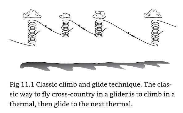 But soaring for longer distances requires finding someplace en-route where the air is rising to restore lost altitude. Therefore, the progress of a cross-country glider trip looks like the picture on the right.
You might think that the optimum would be to climb to the maximum possible height in each of those thermals. But while you are spiraling in a climb, the other racers may be speeding toward the finish line. The higher you climb, the faster you can fly between thermals, but the longer time you spend in thermals making zero progress toward the destination on the ground. The optimum is a trade-off between speed and time. Paul MacCready was the one to figure out what the optimum was. He related it to the expected rate of the climb you will get in the next thermal. Not the thermal you are in but the next thermal. I confess, that I don’t understand that logical leap, but I do accept it as the correct answer.
Before seeing how to use the MC, we need to study the glider’s polar curve.
The Polar Curve
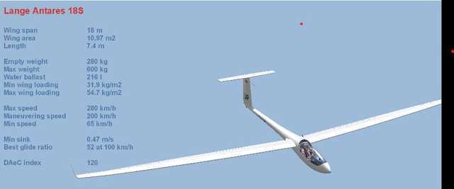
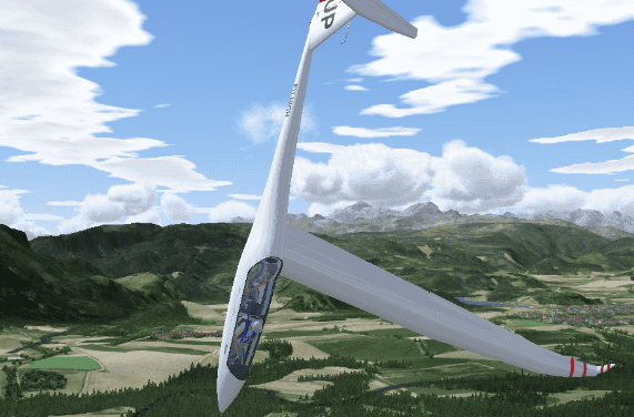
The Lange Antares is a modern high-performance racing glider.
Below you see the polar curve for the Antares 18S. It plots horizontal speed versus vertical speed. The optimum speed to travel from point A to point B is found by taking a line from the origin tangent to this curve. In the picture, we show that by the dashed line. The glide ratio for that dashed line shows as 51.2, the optimum speed to fly as 97 km/h, and the sink rate as 0.53 m/s. The optimum gets us to point B in minimum time.
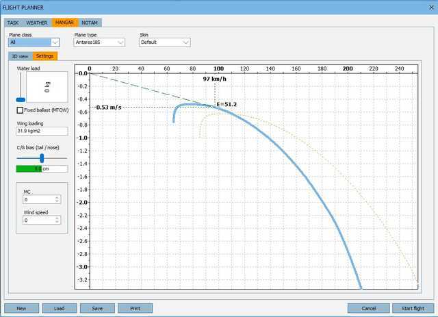
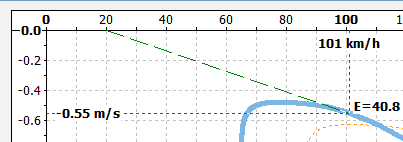
If we have a tailwind or a headwind, it shifts the intercept point of the dashed line with the horizontal axis left/right. For example, with a 20 km/h headwind, the optimum speed increases to 101 km/h.
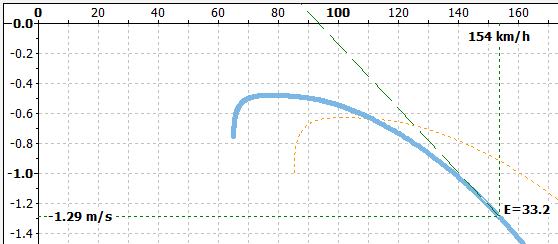
In rising or sinking air, the effect shifts the intercept of the dashed line with the vertical axis up/down. That intercept of the dashed line with the vertical axis is called the MacCready Number, or MC for short. Below, I changed the MC to +2.0. As you can see, the optimum speed to fly increased to 154 km/h and the glide ratio reduced to 33.2.
A simple way to think of MC as an optimism factor. The optimist expects lots of lift and he changes MC to a more positive value. The pessimist expects only sinking air and he sets MC negative. The pragmatist sets MC=0. Pragmatists and pessimists seldom win races. Optimists sometimes don’t finish and may be forced to land in a cornfield. When flying over mountains instead of fields, a forced landing could be fatal, so the prudent pilot would use a lower MC over mountains.
The MacCready Ring
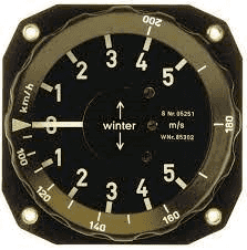
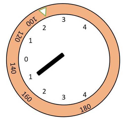
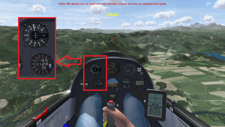
Another intellectual giant leap that Paul MacCready made was to translate that optimization strategy to something completely practical for a pilot to use in the cockpit without the aid of a computer. We call it the MacCready rings seen as the brown part in this picture.
The ring fits co-axially with the vario. In this case, the numbers of the ring correspond to a speed in km/h. The distance between the numbers is calibrated to match the polar curve of this glider. The pilot turns the ring so that the arrow points at the vertical speed in m/s that he expects from the next thermal. We call that the MC number.
Here’s an example. The pilot rotated the ring to MC=2.2, and we are in sinking air -1 m/s. The ring shows that the speed to fly about 152 km/s.
It could hardly be simpler. Simple is precisely what the pilot needs. I think of it as genius. It matches optimization theory with strategy and with the ergonomics of a human interface that a pilot can easily understand how to set and how to apply, and it accomplishes all of that with a simple piece of plastic. If they had Nobel Prizes for engineering, I think the MC ring and Paul MacCready should have been nominated.
The ring also makes it easy to incorporate human psychology as part of ergonomics. The race committee may say, “Today in the interest of safety, all race contestants shall set their rings at 1.5.”
The Electronically Integrated Vario
Here you see a pilot’s eye view from the Condor 2 soaring simulator. Note that there are two vario instruments (Also shown magnified in the inset.), one pneumatic and the other obviously electronic. There is also a PDA on the right side. I guess that dates the simulator as being 20 years old. Today, we would use a smartphone or a tablet, not a PDA.
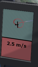 The PDA has several screens. One screen (not shown) is like a moving map; like the navigation system in your car or the Google Maps app on your phone. Another screen (shown here) we use for use in thermals. It displays the history of your recent GPS coordinates, in a bread-crumb-trail fashion. The crumbs are also color-coded. Red shows rising air, and white shows still air. The pilot uses this screen you to try to find the center axis of the thermal. Remember that looking out the window provides no visual clues to where these thermals are. This screen also shows your average vertical speed in this thermal as 2.5 m/s. It is good data because the number 2.5 depends both on the air mass motion and on the skill of the pilot in circling the thermal. 2.5 is your first guess of how to set the MC for the next thermal, but MC=2.0 might be more conservative.
Still another screen on the PDA shows cross-country information. At the top, you see the current MC setting, followed by two numbers DH and DDH. DH is your current height above the next waypoint. The PDA’s calculated prediction for your height when you reach that next waypoint we call DDH. It can be plus or minus. The three screenshots shown were taken a few minutes apart but with three values of MC. Note the relationship between MC and DDH. (What about TTG and ETA? I haven’t studied those yet.)
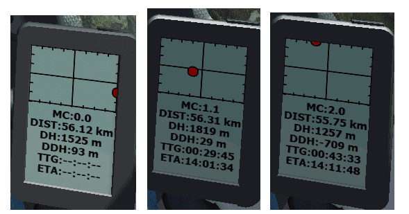
The red ball on that screen also aids the pilot. When the ball is on the crosshairs, then you are heading the right direction and the right speed to arrive at the waypoint at the predicted DDH height. As you can see, the ball position moves when we change MC.
Excessive Height
Excessive height can be bad. Pilots racing for the finish line may find that they have excessive height. That tempts them to fly as fast as they can, trading excessive height for speed. ##V_{NE}## stands for velocity to never exceed. It has happened that racing gliders have broken up at or near the finish line because pilots exceeded ##V_{NE}##. : Modern gliders are magnificent, but also fragile.
Integration
Now for the integrated part. The pilot can put the electronic vario in a mode that communicates with the PDA. In that mode, the vario no longer indicates vertical speed. It shows zero when your airspeed is optimum (i.e. speed to fly). If you enter rising air, the optimum speed is slower, in sinking air the optimum speed is faster. Watching that needle guides the pilot to increase or decrease speed. If he increases the MC on the PDA, the optimum speed will be faster. In other words, it is an adaptive MacCready ring. The old-fashioned ring doesn’t know how far away your destination is. The electronic adaptive one does know that. The pilot can then use the pneumatic vario, the airspeed indicator, the electronic vario, and the PDA screen in an integrated fashion. I think that is pretty cool.
The Angle of Attack Indicator
I have not seen an angle of attack (AOA) indicator in a glider. However, the AOA of the 737 MAX figured prominently in the Physics Forums thread about the 737 MAX accidents. Let’s look at it here because it is closely related to this pitot-static topic.
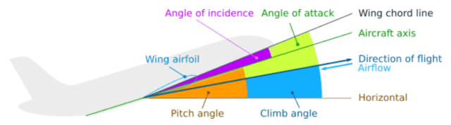 In fluid dynamics, the angle of attack (called AOA, or α, or alpha) is the angle between a reference line on a body (often the chord line of an airfoil) and the vector representing the relative motion between the body and the fluid through which it is moving. In this article, we said much about rising and sinking bodies of air, but this graphic illustration is for the case of still air. It should be clear that the airplane’s nose does not necessarily point in the direction of motion, especially as we approach the stall speed.
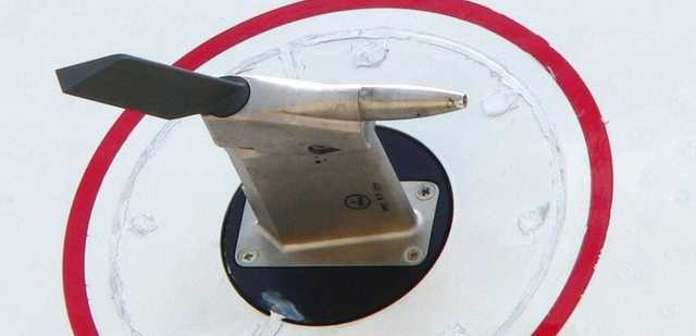
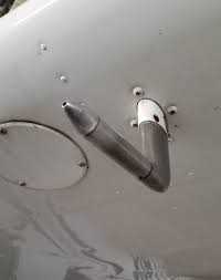
An AOA sensor is yet another pitot-static device. The one in the picture appears to also have a wind vane that can move to show the angle of the airflow streamline
 The AOA Principle
 The AOA Principle
Now, let’s revisit this figure. Focus on P1 and P2. It should be clear that when the AOA is zero, P1 has more pressure than P2. But if the motion of the plane was 45 degrees downward while the airplane axis remained level, the air would be blowing directly into tube 2, and P2 would have more pressure than P1. That is the principle of AOA measurement. The details, of course, are more complicated than the principle.
Free Thinking
Thinking like an engineer, I would like to generalize. Measure the pitot and static pressures and wind vane angles at many different angles, and many locations on the plane, and the 3D GPS coordinates, and inertial sensors. Bring all the measurements you can into a basket of partially redundant measurements. From that, we could extract state estimates of many performance parameters: altitude, airspeed, VSI, vario, AOA, and more. We could also estimate which sensors are malfunctioning if any. We call that “state estimation”. It is used in many other engineering fields. State estimation is the opposite of the KISS principle (Keep It Simple Stupid). I am fond of KISS, but there is no reason why the pilot can not have both KISS and anti-KISS instruments at the same time.
Conclusion
Are you looking for a really fun thing and an affordable thing to do during the COVID crisis? A capable PC, plus a joystick, this soaring simulator has a lot to offer. Even if you never flew before, the simulator can help you to learn, and learning to fly a glider keeps you much closer to physics than flying an airplane.
Dick Mills is a retired analytical power engineer. Power plant training simulators, power system analysis software, fault-tree analysis, nuclear fuel management, process optimization, power grid operations, and the integration of energy markets into operation software, were his fields. All those things were analytical. None of them were hands-on.
Dick has also been an exterminator, a fire fighter, an airplane and glider pilot, a carney, and an active toastmaster.
During the years 2005-2017. Dick lived and cruised full-time aboard the sailing vessel Tarwathie (see my avatar picture). That was very hands on. During that time, Dick became a student of Leonard Susskind and a physics buff. Dick’s blog (no longer active) is at dickandlibby.blogspot.com, there are more than 2700 articles on that blog relating the the cruising life.


In addition to the functions described in the article, collision avoidance is an important new addition. Compare that to TCAS collision avoidance in airliners.
View attachment 270277
With all this digital stuff, a totally new control input device is needed in addition to stick and rudder; a mouse. The picture shows the built-in mouse for use by the pilot.
View attachment 270278
Not shown is a spot satnav device that attaches to the pilot's parachute. It has an emergency SOS button, and also a button to send texts to your friends saying, "I'm OK" or "I landed at GPS coordinates X,Y, please come with the car and the trailer. That's wonderful when out of cell phone or VHF radio range.
View attachment 270280
By the way, the idea of having a device that sends prearranged messages at the push of a button was invented by Thomas Edison. For example, "Help, I've fallen and I can't get up." Edison's device had 10 possible messages, so Edison also invented the device below to make it easy for untrained customers to use. I love the idea that a satnav device still uses Edison's invention.
View attachment 270279