How to Recognize Split Electric Fields
Table of Contents
Introduction
In a previous Insight, A New Interpretation of Dr. Walter Lewin’s Paradox, I introduced the fact that there are two kinds of E fields. One (Em) is generated whenever a source of emf is produced. The other (Es) is the electrostatic field. The Es field always terminates on free charges; the Em does not. Es is a conservative field like gravity; Em is not. The circulation of an Es field is always zero. The circulation of an Em field is always finite.
My intent is to reveal the existence of the two fields in a number of situations and, more importantly, show that in most cases this approach is the only acceptable one if conflict with established physical laws is to be avoided.
The Start
The total electric field ## \bf {E = Em + Es} ##.
We define an electric field E as the force F on a stationary charge: ## \bf E = \bf F/q ## with q ## \rightarrow 0 ##. By this defnition,all Em and Es in all of the examples cited below are electic fields.
We also state that Ohm’s law for fields ## \bf j = \sigma \bf E ## always holds.
We further state that “voltage” is reserved to the line integral of the Es field only. A voltmeter can get an incorrect voltage reading if its circuit is impacted by the emf generator (see below). A voltmeter is modeled as an arbitrarily high-value resistor r. The voltmeter reading strictly follows Ohm’s law: V = ir, i = current thru r.
We further recognize the applicability of the Helmholtz Decomposition Theorem to electric fields which states that every E field can be decomposed into a conservative field ## \bf E = -\nabla \phi ## and a solenoidal field ## \nabla \cdot \bf E = 0 ##. From this follows that every E field can be written as ## \bf E = -\nabla \phi + \nabla \times \bf W ## where ## \bf W ## is the electric vector potential.
Em will be recognized as the div-free field while Es is the curl-free field.
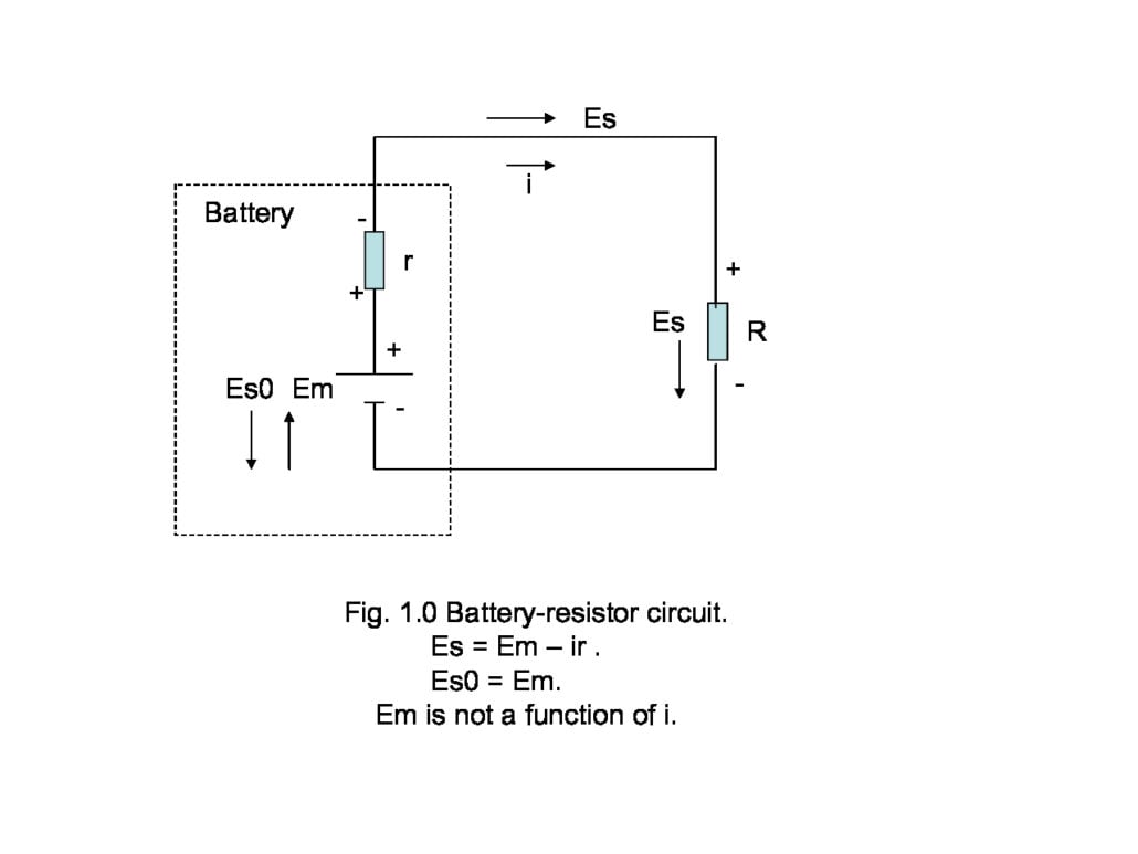
The first and admittedly controversial example is that of a chemical battery. It’s controversial because most folks consider that there is only one E field in the battery, pointing + to -, which corresponds to my Es.
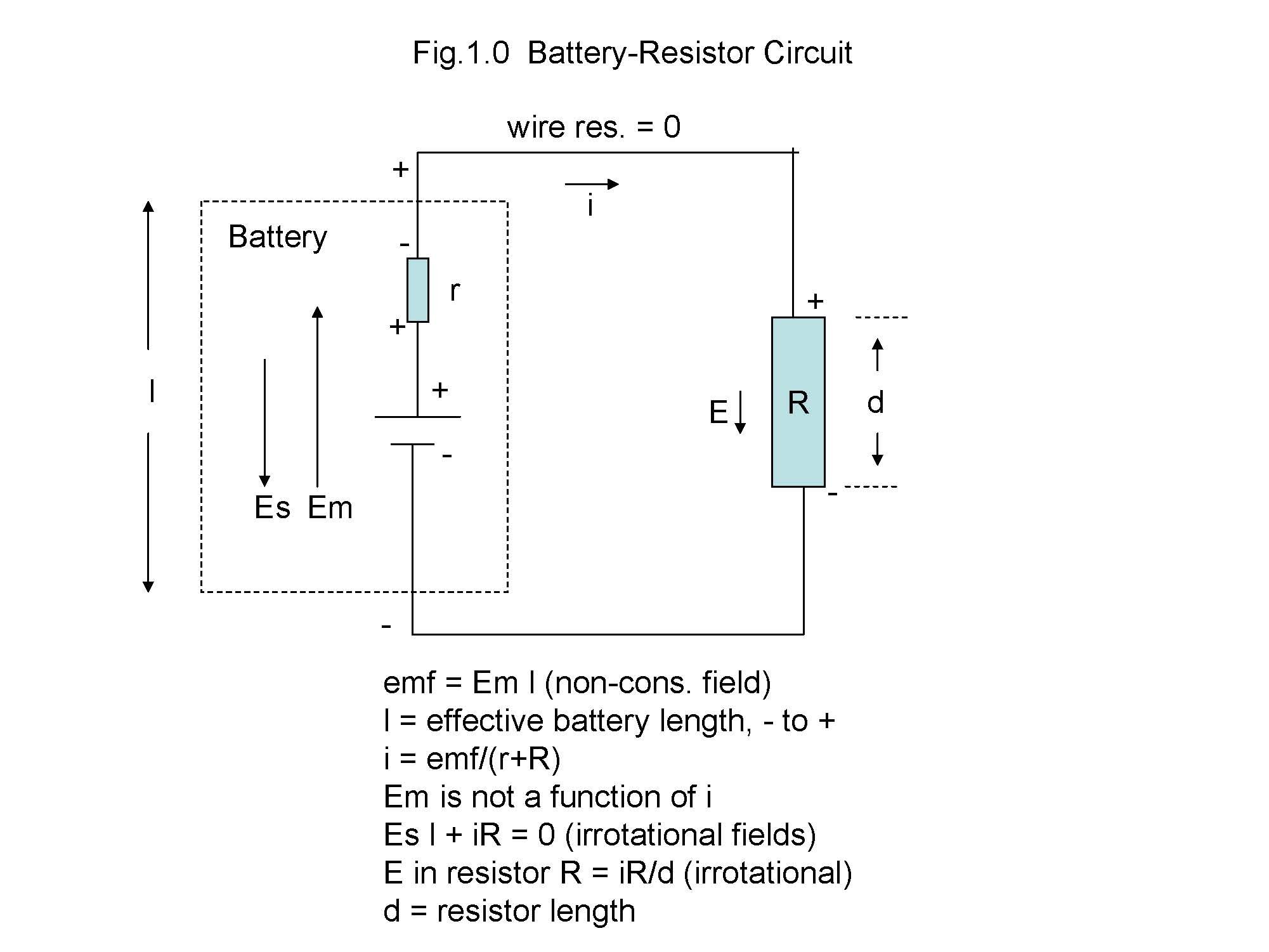
There is in fact also an Em field inside the battery, pointing – to +-. This Em field, line-integrated over the effective length l of the battery, = emf.
In the absence of current draw these two E fields are of equal magnitude so the net E field is zero. But with current i, internal battery resistance r and external resistor R the Es field is reduced to ## Es = (emf – ir)/l, i = emf/(R+r) ##. ## \oint \bf E \cdot \bf dl = \oint \bf Em \cdot \bf dl = emf ##; ## \oint \bf Es \cdot \bf dl = 0 ##.
Next, let us look at a conductive ring of asymmetric resistance around the ring surrounding a time-varying B field (Fig. 1.1, the “Farady setup”). We get both Em and Es fields in the ring due to the differing resistances in the two ring halves.
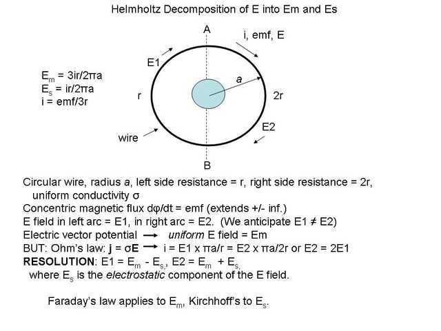
The electric vector potential clearly indicates that the induced E field is uniform around the entire ring. This goes beyond Faraday who simply says that the circulation of the E field around the ring is the emf .Thus, any E field present in the ring other than the induced field (Em) must by Helmholtz be a conservative field (Es).
The circulation of Em = emf = ## -d\phi/dt ## per Faraday, while the circulation of Es = 0 around the ring per Kirchhoff.
The voltage from top (+) to bottom (-) of the ring is ## \int_A^B \bf Es \cdot \bf dl = ir/2 ## in either direction and can be measured by a voltmeter provided the normal to the plane of the meter’s leads and body are orthogonal to the B field, i.e. suspended directly above the B field source. Any other juxtaposition will give an erroneous voltage reading.
Note that the Em field is that set up by the ## d\phi/dt ## field in vacuo and is not altered with the insertion of the resistive ring. The asymmetric ring produces new Es fields only.
Let us look at a third example of emf generation (Fig. 1.2 below).
L is an inductor wound of zero-resistance wire in a circuit with a battery and resistor. Current I will flow when switch S is closed. (Fig. 1.2).
.
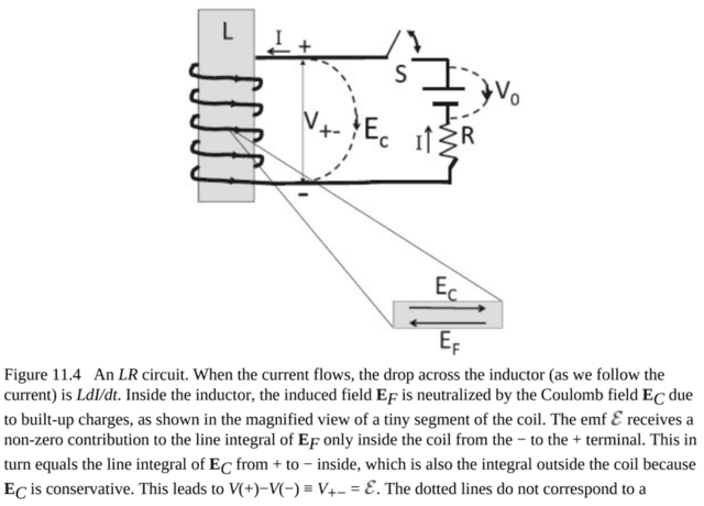
Per the figure we identify two E fields inside the wire: a non-conservative ## \bf E_f ## and an irrotational ## \bf E_c ##. (Shankar’s ## \bf E_f ## is my ## \bf Em ## & his ## \bf E_c ## is my ## \bf Es). ##
If we integrate the E field over the solenoid’s wire, closing the loop from the bottom end of the solenoid, thru the wire and back to the bottom end (path ##E_c##) we obtain ## \oint \mathbf E_f = L dI/dt. ##. whereas ## \oint \bf E_c = 0 ## (zero-resistance wire assumed).
R. Feynman covers the same issue in Vol. II chapt.22 of his famous Lectures and gets the same answer but his rationale is wrong because, by ignoring split fields he implicitly denies ## \oint \bf E \cdot \bf dl = -\partial \phi/\partial t ## for the circular E field inside the wire, stating simply that the E field is identically zero. In reality two equal and opposite E fields, Em and Es, cancel each other. Letting E = Em satisfies the above equation.
We can, analogously to the battery with finite internal resistance, cover the case where coil wire resistance r is finite. Es is similarly reduced to Em – ir/l, l = coill wire length, and the coil voltage reduces to V = L di/dt – ir.
The solenoid is the exact analog of the battery: both create emf, one chemically and one magnetically. Both hold equal and opposite Em and Es fields. Both hold net zero E fields.
Next example: that of a conducting bar of length l moving orthogonally within a constant B field with constant velocity v (Fig. 2a). Imagine you are sitting on the bar; you have no idea you’re “moving”, yet an emf = Bvl is generated, Simultaneously, an equal and opposite E field must also be present; the net E field in the bar must be zero. This must be the electrostatic field Es. A voltmeter configured so its leads are not impacted by the B field would read the integrated Es field, numerically the emf.
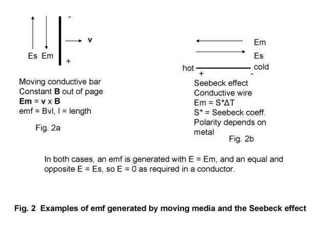 Last example, and perhaps the most basic: the Seebeck effect (Fig. 2b). In this case the emf is generated by a temperature difference between ends of a wire. Good choices would be iron or constantan. Again, the wire must have zero E field within it yet an emf is generated and can be measured with a voltmeter, this time without any concern as to meter circuit disposition. Separate equal and opposite Em and Es fields are again the only cogent theory.
https://en.wikipedia.org/wiki/Thermoelectric_effect#Seebeck_effect
We see that in all examples there is curl. By Stokes, whenever the circulation of an E field is non-zero there must be net curl within the peripheral area bounded by the circulation path. Curl may also be in the E field itself as in the inductor. In general, all sources of emf have associated non-conservative fields with curl somewhere.
Summary
In emf-generating situations the possible existence of separate electric fields should be recognized and appreciated. An Em field is always present; an Es field is often also as exemplified above..
emf is the line integral of the Em field over the length of the conductor. This can be a circulation integral as in the Faraday setup and the solenoid wire, or it can be a line integral as in the other examples.
As corollary the existence of curl in every emf production must also be admitted.
Assuming cylindrical coordinates and a = radius of a cylinder, for a right circular cylindrical solenoid, curl is everywhere including in the wire itself. For a .battery, moving bar or Seebeck wire, curl exists within a closed contour including the Em field and is ## \nabla x \bf E_m = – \partial \mathbf E_m/ \partial r ## in the ## \bf \theta ## direction. The right-hand side evaluation depends on the nature of the ## E_m ## transition region about r=a.
Comments, questions, critique welcome. That’s how we learn.
Read my next article: https://www.physicsforums.com/insights/misconceiving-mutual-inductance-coefficients/
(Extensively edited 25 jun 2020).
AB Engineering and Applied Physics
MSEE
Aerospace electronics career
Used to hike; classical music, esp. contemporary; Agatha Christie mysteries.


An excellent & detailed description of electric fields in a chemical battery is at https://www.av8n.com/physics/battery.htm#fig-battery-rest-field
Fig.5 shows the Es and Em fields canceling each other to give a net zero internal field, while the + to – line-integrated internal (or external) Es field is the emf. The two Es fields’ circulation is zero as required for an electrostatic field..
In fig. 7 current is flowing and the internal Es field is reduced by the internal resistance by an amount ir with r the internal resistance and i the current. As a consequence the Em field provides a net battery internal E field with direction from – to +.